HIGH SPEED SHOCK TESTING OF AERODYNAMIC JOURNAL BEARINGS
KEYWORDS
- Shock test
- Impact measurement
- High-speed imaging
- Ceramic bearing pads
TEST SET-UP
OUTPUT
- Bending behavior of the pad during impact
- Crack initiation and propagation
- Relative movement between pad and housing

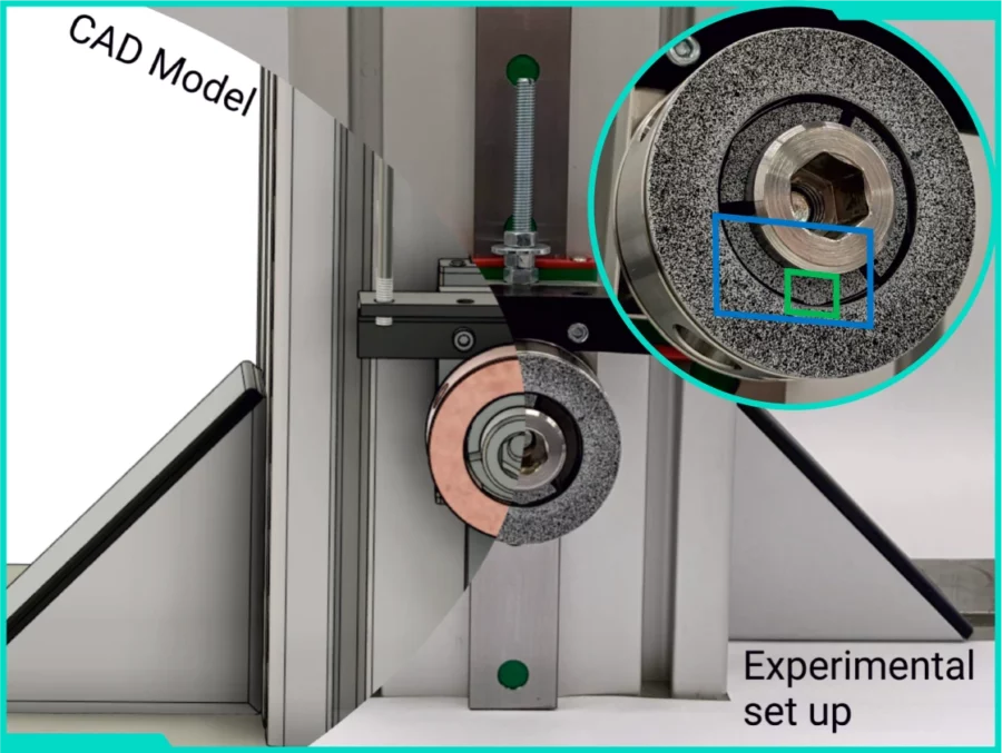
The experiment was carried out to determine the shock resistance of the ceramic pads in aerodynamic bearings developed for high-speed machinery. The aim was to determine the height in the drop test at which the ceramic pads would not yet fracture and to investigate the bearing behaviour at impact as a basis for calibrating the finite element model. The experimental setup consisted of a bearing mounted on a fixture that moved freely along a rail after being released at a certain height. The fixture contained a part representing the shaft on which the bearing was mounted, which consisted of a housing on the outside and three ceramic pads on the inside, on which a speckled pattern was applied. Between the housing and the pads were placed springs for partially absorbing the shock. A Fastcam SA-X2 HS camera with a framerate of 100 kHz at 0.1 MPx and 200 kHz at 0.03 MPx was used for image acquisition, along with a 105 mm (first case – global) and 200 mm (second case -local) macro photographic lens and GSVitec high-power flash lights.

Before measurement the calibration grid was captured in the global view for system calibration. For the local view, only the Scale calibration using the known dimension of the pad was utilized. During the measurement, the camera captured 1 s of footage during the drop and impact for each sample, which was subsequently processed using Alpha DIC software.
WHY CHOOSE X-SIGHT?
- Powerful and easy-to-use Alpha DIC software allows to input data from high-speed camera and perform post-processing using wide range of analytical tool to extract valuable information from data.
TOOLS AND RESULTS
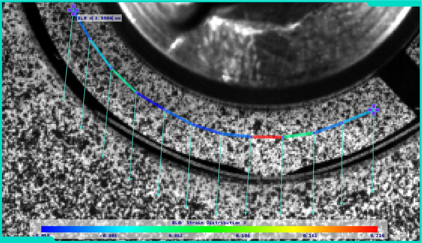
First of all, the behavior of the segment was studied in the global view using the Bend Line tool, offering a representation of the movement of individual points by means of arrows that can be enlarged for rendering in a certain scale, as in the picture on the right. It also allows you to calculate the strains between its points along with their color representation.

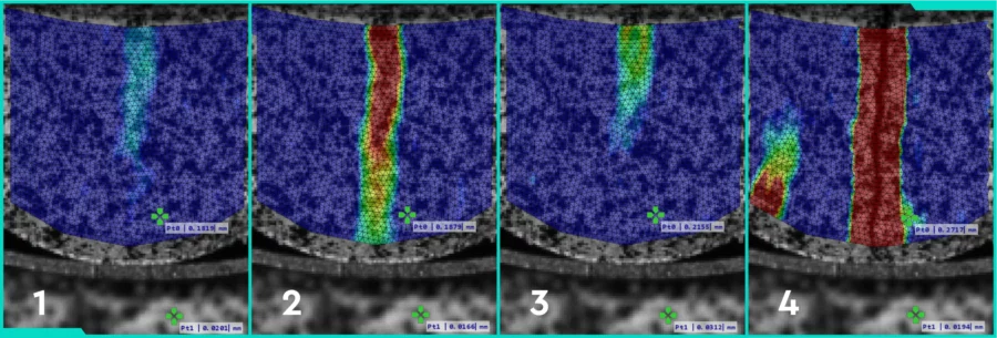
The DIC Area tool was then used in the local view, which allows the deformation field to be examined over the entire region of interest. In this case, horizontal strain proved to be the appropriate quantity to investigate pad rupture at impact, specifically the site of crack initiation and propagation. The time elapsed between the first and the last (fourth) pictures was 0.2 ms.

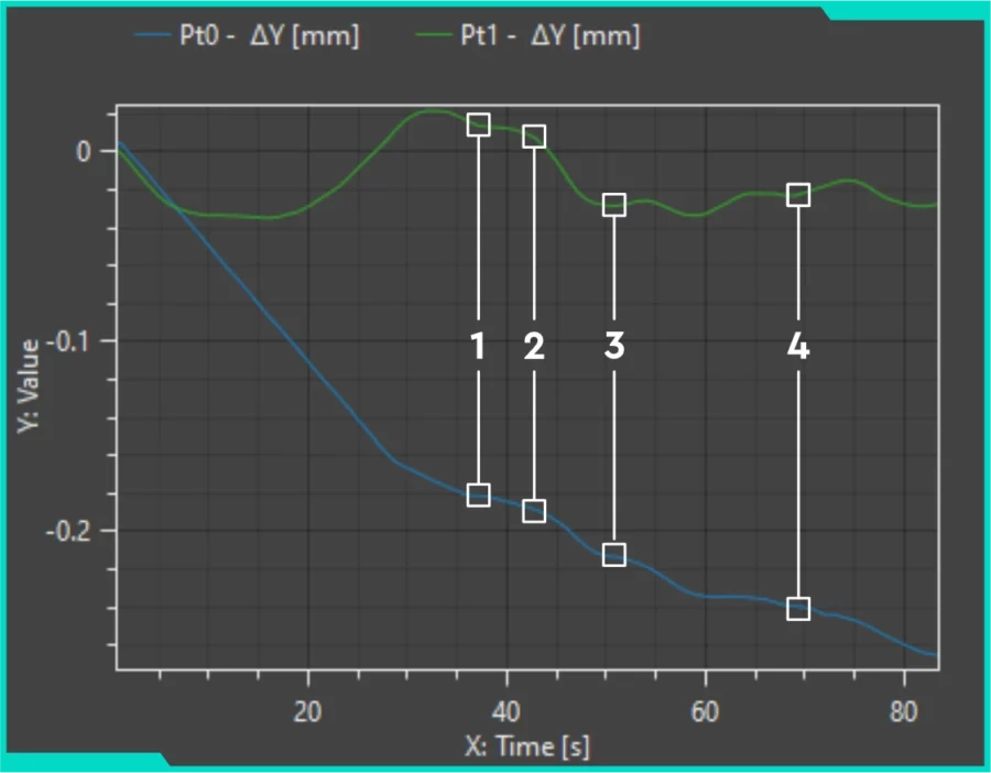
In the same view, the Point Probes, one on the pad (blue in the graph) and the second on the housing (green), were used to investigate their relative movement by rendering their change in vertical coordinate. In addition, the moment of crack initiation could be explored, as the moments (1 – 4) belonging to the above pictures could be marked on the graph. This leads, for example, to the interesting finding that the initiation of the crack (between 1 – 2) occurs at the moment when the pad with the shaft is still falling down, but the housing has already hit the ground and is now moving against it.

🗎 Download PDF version of this report here.