3D PRINTER HEAT BED DEFORMATION
KEYWORDS
- Thermal deformation
- Heated glass bed
- Displacement and strain distribution
- Temperature gradient effects
- Borosilicate expansion behavior
- Related standard: ASTM E1461
TEST SET-UP
OUTPUT
- 3D displacement field of the glass plate during heating
- Surface strain evolution in X/Y directions
- Real-time deformation tracking over temperature range
- Insight into thermal bowing and expansion asymmetry

INTRODUCTION
A significant aspect of our research is measuring the 3D printer’s heat bed displacement, which is conducted using advanced tools such as an IR camera and DIC (Digital Image Correlation).The DIC measurement, a well-established technique, is not just a theoretical concept but is deeply embedded in practical engineering processes. It is commonly used in testing designed components, material testing, and establishing movements or deformations of various specimens, prototypes, or large objects.
A new frontier of DIC measurements has recently started to be explored: infrared cameras supported DIC testing. Even more recently, we have also decided to dive into this new area of optical testing. In this report, we have taken a deeper look at what happens on the 3D printing heating sheet when considerable heat is applied to it by the 3D printer.
MEASUREMENT
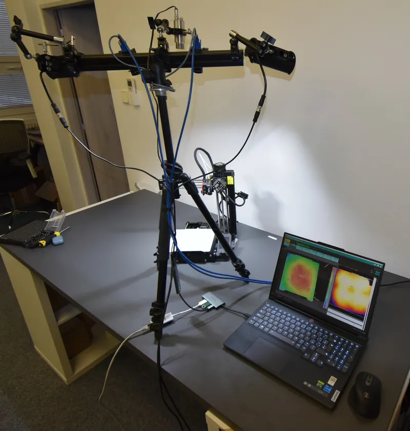
The picture above shows an infrared camera during the measurement. Once the IR camera and Alpha DIC software, a crucial component of our measurement setup, were connected and the systems were calibrated, the test could begin. The DIC camera and the Alpha DIC software played an important role, providing insights into where it might be essential to place point probes within the DIC area.
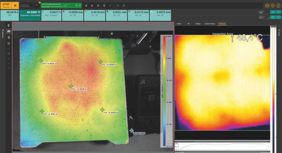
It is important to emphasize that we are working with IR camera vision within real-time measurement. For post-processing, we focus on the maximum temperature tracked by the IR camera, which is in the following diagram.
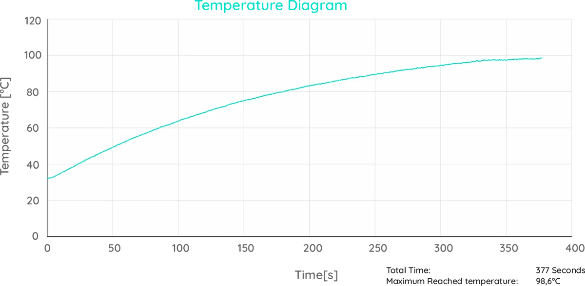
As digital input into Alpha DIC, we can base all the following diagrams on the changing temperature, providing a more detailed view of what is happening during the heating process.
INSPECTION
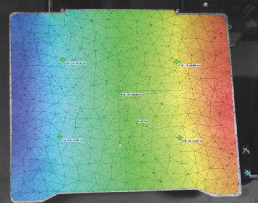
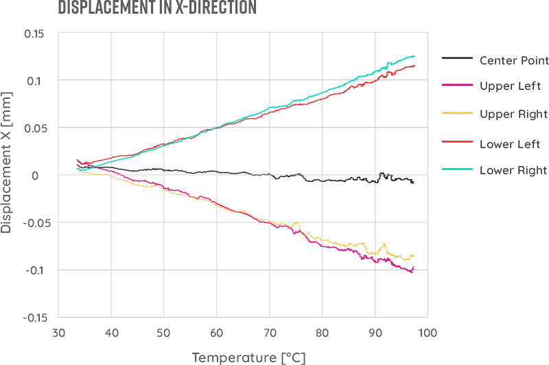
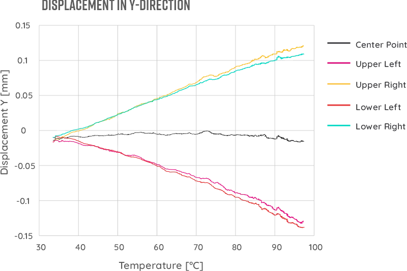
The best way to understand what is happening to the printing sheet is to inspect it by dividing it along the axes along which the movement is occurring. Starting with the X and Y axes, the displacement here is quite uniform, as is clearly visible in the following picture.
The way both axes look is pretty much correspondent to standard heat expansion laws, with both sides stretching in the opposite direction. The displacements are very similar in the diagrams, and if the positioning of our probe points were symmetrical to the coordinate system, we could probably see the diagram lines stack on one another. Of course, little to no materials are homogeneous, so complete overlapping of diagram lines is unlikely, and the same goes for the linearity of the curves.
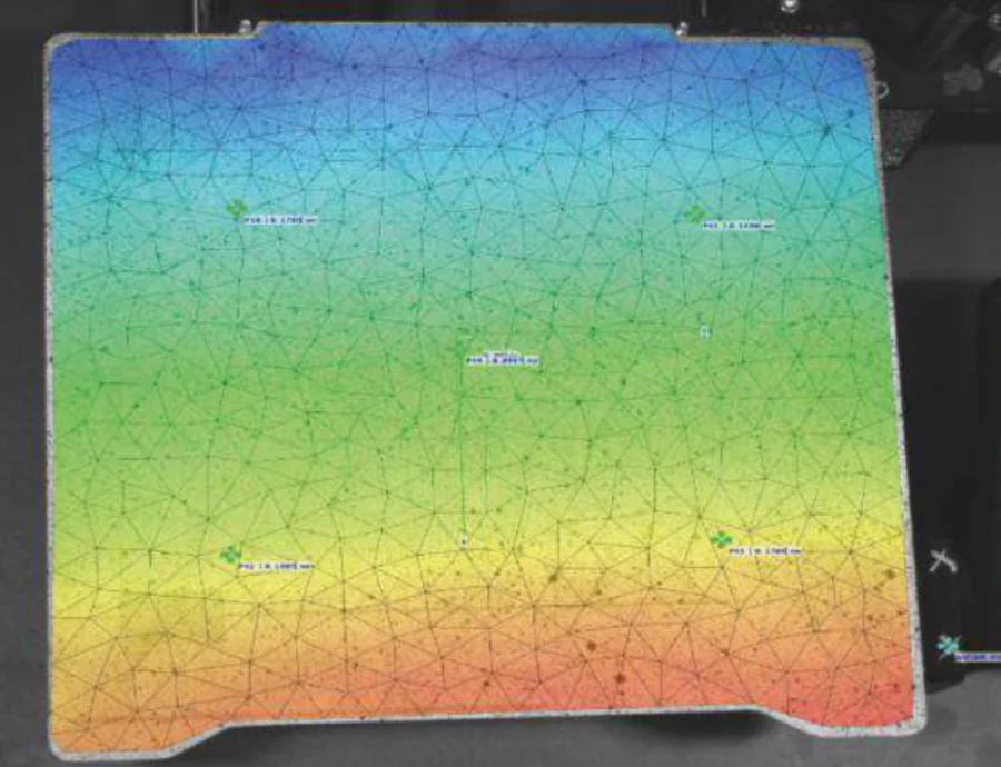
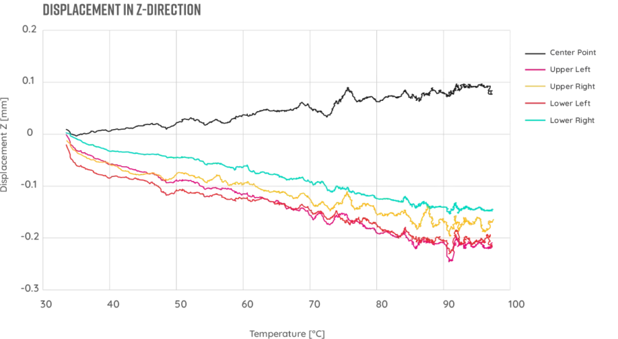
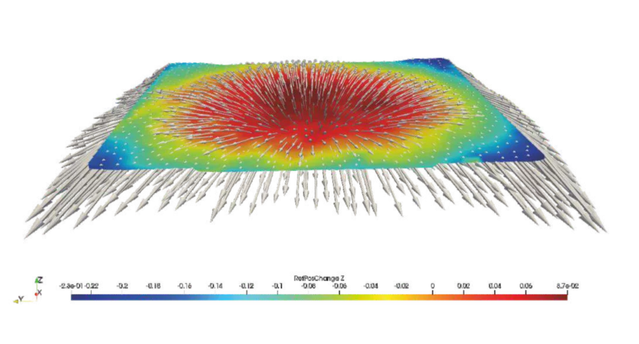
Displacements in the Z-axis—towards the camera—do not behave as predictably as the other displacements. From the picture below, it is easily noticeable that the center has a more uniform displacement, which, according to the data, is about 0.1 mm at maximum. The corner points move away from the camera in the negative Z direction, as seen in a 100x exaggerated 3D view.
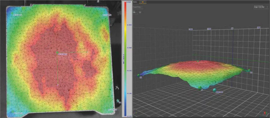
The probable cause of this effect is that the heating elements are expanding the entire 3D printing table along the X-axis while the temperature distribution lags behind. This results in the corners expanding sometime after the center of the sheet has expanded. The probe points in the corners have moved during heating by anywhere from 0.14 mm to about 0.2 mm.
CONCLUSIONS
The testing of the 3D printers’ heat bed conclusions is that the printing surface is not flat but very slightly curved. The corner areas are notably slanted downward, while the center bulges. However, this movement during heating is corrected by the calibration of the 3D printer just before printing. Based on several point locations, the printer recalculates the surface and adjusts the G-code to ensure that the printing head never catches on the printing surface.
🗎 Download PDF version of this report here.
The thermal measurement functionality used in this application report was developed with the support of the Technology Agency of the Czech Republic.