Analysis of Spruce wood Deformation During Compression Testing
KEYWORDS
- Compression test
- Spruce wood
- video extensometer
- wooden fibre
TEST SET-UP
- 4105-3D extensometer
- Universal testing machine ZD-40
- Stochastic pattern kit
- Alpha DIC® modules: AX, DIC
- Measuring tools:
- DIC Area
- Line probe
- Point probe
- DIC Area
OUTPUT
- Stress strain diagrams
- Strain concentration maps
- Elastic modulus
- Yield stress
- Ultimate compression stress

In the manufacturing of composite boards and other engineered wood products, the efficiency and quality of production are strongly influenced by the mechanical properties of the raw material. If these properties are not accurately characterized and accounted for, the overall performance of the production process can be significantly compromised.
To assess these characteristics, appropriate mechanical testing is required. During composite board manufacturing, industrial presses apply compressive force to the wood material to achieve sufficient bonding and densification. Therefore, compression (or compaction) testing is particularly relevant for evaluating material performance under such conditions.
Since wood exhibits anisotropic behavior, it is essential to conduct tests with respect to different fibre orientations. Typically, specimens are tested at angles of 0°, 45°, and 90° relative to the loading axis of the testing machine to capture the full range of mechanical response.
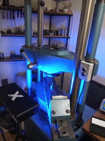
Inspection and evaluation
It was observed that wood exhibits anisotropic behaviour, deforming differently along various directions. To accurately capture local deformations, the evaluation region in the 3D video extensometer with post-processing software was configured so that two sides of the specimen are visible. This adjustment was necessary because small wood specimens tend to gradually chip or shear near the edges due to surface slippage along the compression tool, potentially generating unwanted deformation extremes.
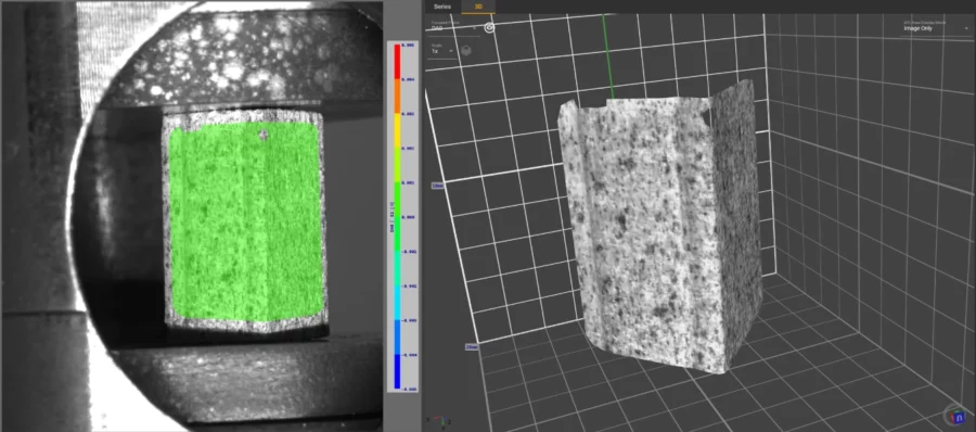
As testing progressed, localized splitting along the wood fibres was observed across all fibre orientations. In some instances, slight sliding occurred along these fracture lines. Despite these failures, the material retained partial internal cohesion and did not completely separate. This gradual failure was accompanied by a slow decline in deformation resistance, indicating that the structural integrity had been compromised. Beyond this point, the material’s behavior became increasingly unpredictable.
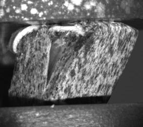
In the 0° direction, the wood sample initially showed a uniform distribution of compressive stress, increasing steadily within the elastic range up to a subtle yield point. Beyond this, the material entered a plastic phase, where resistance to deformation remained relatively stable. The end of the test was determined at the point where a definite fracture can be observed. Following image shows this moment for the specimen no.1.
Following diagram shows the stress-strain dependencies that were measured. After yield stress is reached a long stable area of plastic deformation is observed upon which a sudden splitting occurs.
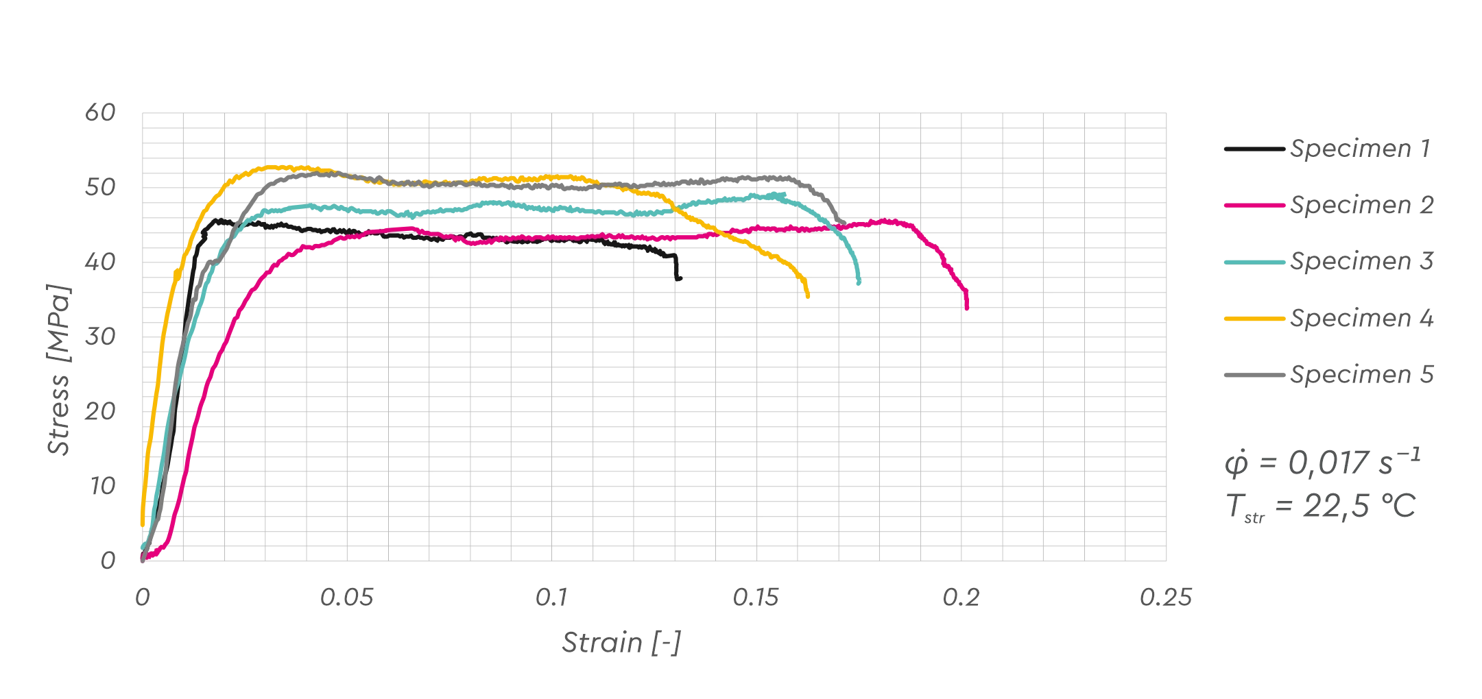
For consistency all specimen direction were measured five times. Upon which a statistical analysis of the data needs to be performed. Evaluated parameters were Yield stress, Ultimate compression stress and modulus of elasticity. During the testing of a relatively stable behaviour occurs, but mechanical properties still vary in a significant way. With Yield stresses various up to 11%. The calculated parameters are shown in the following table:
| Fibre direction 0° | Mean value | Standard deviation | Minimum | Maximum |
|---|---|---|---|---|
| Yield stress Rp0,2 [MPa] | 30,8 | 3,3 | 27,7 | 35,8 |
| Ultimate compression stress Rm [MPa] | 49,2 | 3,2 | 45,7 | 52,8 |
| Modulus of elasticity E [MPa] | 3191,1 | 872,1 | 2226,3 | 4369,9 |
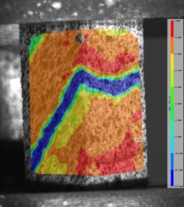
At an angle of 45°, fibre compression begins from the start of the test along one of the planes parallel to the grain. It can be assumed that this represents the compression of the softer (springwood) layer of the growth ring between two harder (summerwood) layers. A strong concentration of deformation soon appears along another plane, also parallel to the grain.
The specimen deforms through gradual sliding along this plane, resulting in the development of localized shear stress. The remaining surface of the sample is subjected to a uniform load.
A brittle fracture occurred along the shear plane.
The sample split into two separate bodies, which slid freely along the fracture surface. The graph has a similar shape to that in the 0° direction, but with significantly lower values of maximum deformation resistance. Failure of the sample also occurred at seemingly random points within the plastic region.
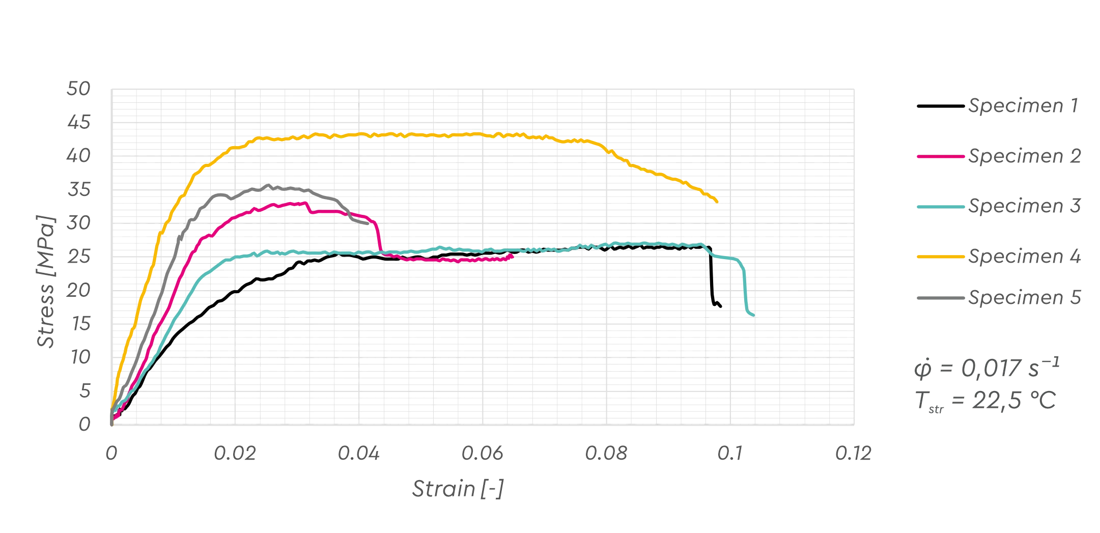
| Fibre direction 45° | Mean value | Standard deviation | Minimum | Maximum |
|---|---|---|---|---|
| Yield stress Rp0,2 [MPa] | 22 | 6,8 | 14,7 | 30,3 |
| Ultimate compression stress Rm [MPa] | 33,2 | 6,9 | 26,7 | 43,4 |
| Modulus of elasticity E [MPa] | 2071,8 | 713 | 1243,2 | 3008,1 |
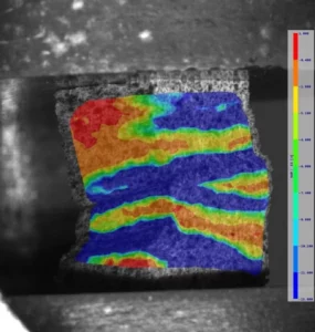
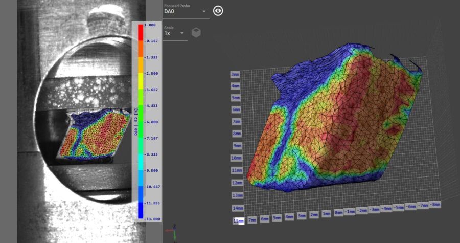
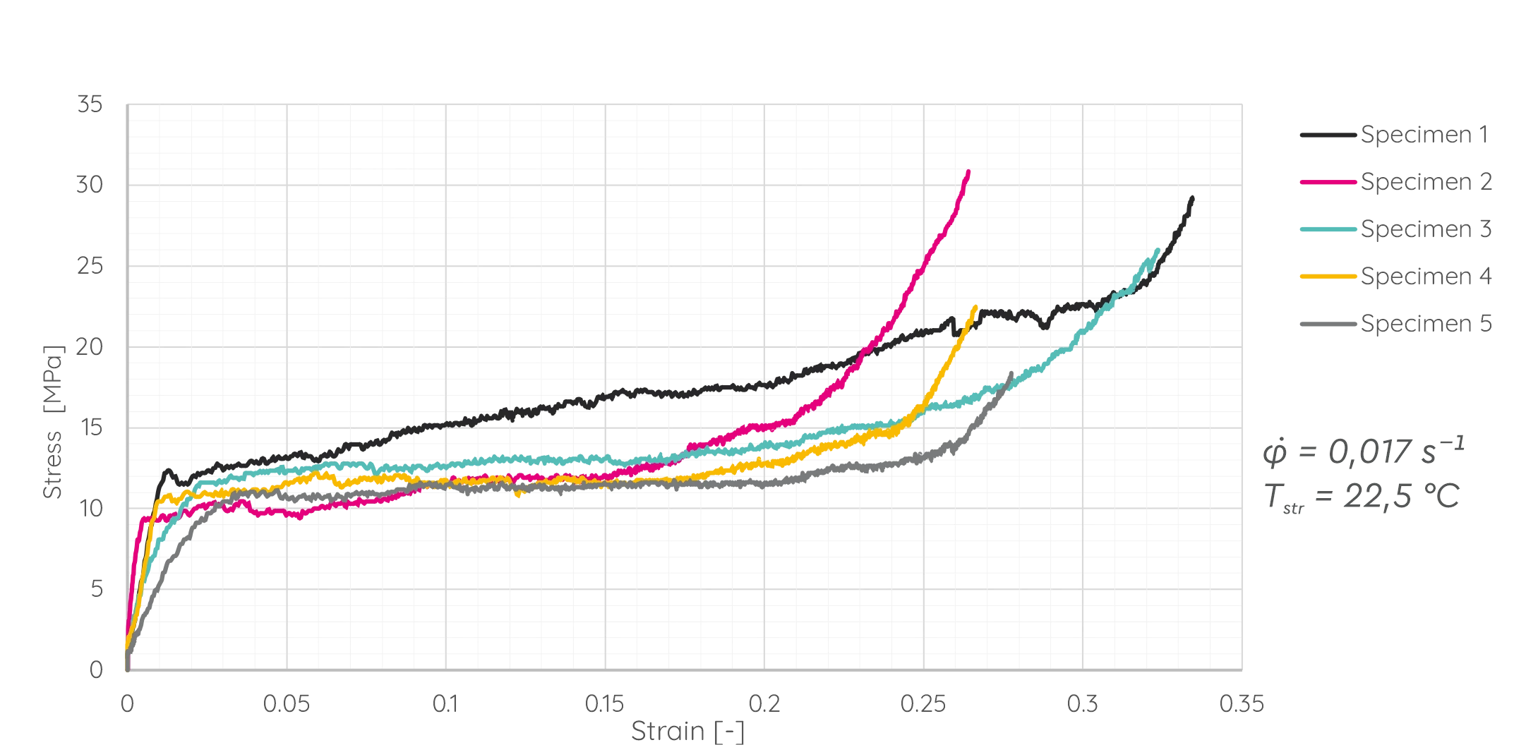
In the 90° direction, i.e., perpendicular to the grain, deformation concentration was again observed from the beginning of the test. In the sample shown in the image, fibres were significantly compressed along at least three planes across the specimen. As deformation progressed, it became evident that on one side, the wood compressed faster in these regions, leading to an inclined deformation of the entire sample. This tilting may have been caused by geometric imperfections in the specimen or by internal structural flaws. In the later stages of the test, waviness appeared on the side surfaces of the samples. Complete failure of the specimen did not occur under this loading direction, but cracks formed at the bulging areas of the wavy surface. In these locations, local stresses can be observed in the 3D visualization. In the 90° direction, the differences in behaviour between individual samples were smaller than in other directions. A linear relationship was observed in the elastic region up to a clearly defined yield point. Beyond that, the material deformed with slight, seemingly linear strain hardening. At the end of this region, the hardening began to increase sharply.
| Fibre direction 90° | Mean value | Standard deviation | Minimum | Maximum |
|---|---|---|---|---|
| Yield stress Rp0,2 [MPa] | 10,9 | 1,2 | 9,3 | 12,3 |
| Ultimate compression stress Rm [MPa] | 15 | 3,8 | 11,8 | 21,5 |
| Modulus of elasticity E [MPa] | 532,5 | 250,6 | 244,5 | 934,8 |
RESULTS
The obtained data presented were used to determine the basic material properties in accordance with the EN 408 standard. As we can see the material properties vary to a high degree between fibre directions. Yield stress determined for 90° Direction is about 66% lower than in the 0° direction and similar trend is observed for other mechanical properties evaluated
| 0° | 45° | 90° | |
|---|---|---|---|
| Yield stress Rp0,2 [MPa] | 30,8 | 22,0 | 10,9 |
| Ultimate compression stress Rm [MPa] | 47,8 | 31,9 | 15 |
| Modulus of elasticity E [MPa] | 3191,1 | 2071,8 | 532,4 |
Compression testing of spruce wood across different grain orientations confirmed its anisotropic mechanical behaviour. The results provide crucial insights for the design and optimization of pressing processes in composite wood production. The differences in yield and ultimate stress across grain directions must be accounted for in structural applications and during the selection of processing parameters.
This Application was done in cooperation with Institute for Manufacturing technologies in Brno University of Technology as a part of Bachelor Thesis.
Download PDF version of this report here