Application info
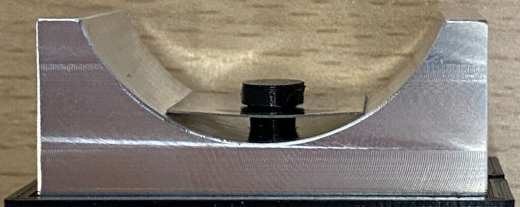
In this experiment, the focus of investigation was a rectangular plate, serving as a low-profile pad support, embedded within a cylindrical frame. The plate offers resistance during deformation, effectively functioning as a spring. The apparatus finds application in aerodynamic bearings featuring tilting pads, contributing to the maintenance of smooth operation amidst varying working conditions. This is achieved by enabling self-adjustment of the bearing clearance through the spring preload. Additionally, the system serves as an auxiliary source of damping.
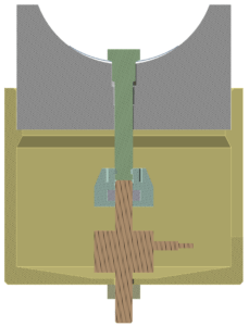
Each bearing imposes unique requirements on the spring parameters. Therefore, the goal of the experiment was to analyze its behavior under load, specifically focusing on the relationship between stiffness and deflection. For this purpose, a fixture was designed to enable controlled compression of the spring by tightening a bolt, with concurrent measurement of the applied force using a force gauge (represented as brown in the model). The experimental data were also utilized to validate the proposed finite element (FE) model.
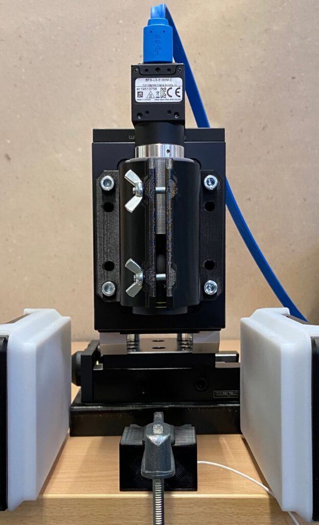
To conduct the measurement, a 5 MPx camera paired with a telecentric lens was utilized. The camera was securely mounted on a stand, facilitating precise focusing of the optical system. Control of the camera was managed through the Alpha DIC software, which also processed the collected data. Illumination of the measured object was achieved indirectly using LED lights, and a diffuser was applied to eliminate glare within the measurement area. Notably, digital correlation did not involve the use of a speckle pattern. Instead, the natural roughness of the surface, featuring distinct traces of material cutting, was leveraged. Calibration was performed using the Scale-only option, utilizing the known dimensions of the measured body.
KEYWORDS
- Small-scale measurement
- Telecentric lens
- Flexible pad support
- Aerodynamic bearing
- Experiment vs. FE Analysis
SETUP
- 5 MPx camera
- Telecentric lens with 0.5 magnification
- Alpha modules: Transversal Strain and Line Strain Distribution
- Measurement probes: Point Probe, Bend Line, DIC Area
OUTPUT
- Shape of the bent spring
- Maximal deflection
- Dependence of spring stiffness on deflection
Why choose X-Sight?
Versatile and user-friendly Alpha DIC software that offers a wide range of analytical tools. Design a professional hardware solution tailored to the application.
Tools and results
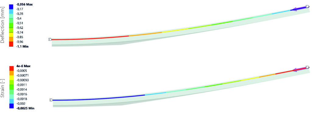
The load was incrementally applied in ten uniform steps before the spring made contact with the fixture. Each step was succeeded by a brief dwell time, during which the attained deflection values of individual points and the maximum deflection were subsequently extracted in post-processing. To facilitate this analysis, the Bend Line analytical tool was employed. This tool not only offers a real-time display of displacement, strain, or curvature values in colored segments between points but also visualizes the direction and relative magnitude of their movement through arrows, akin to displacement vectors


X-Sight DIC – The Bend Line results display (colored segments for Deflection, Strain, Curvature and Displacement vectors)
when the spring is loaded
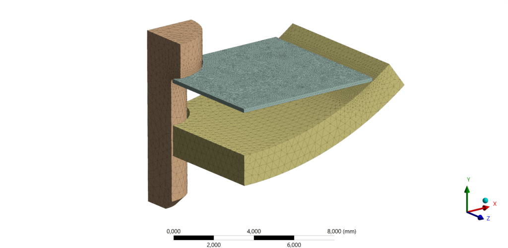
To apply the finite element method, only one quarter of the device was modeled, considering that the apparatus possesses two planes of symmetry. Concerning the boundary conditions (BC), controlled displacement gradually moves the pin downward during the analysis. The cylindrical frame is restricted from radial displacement on the outer cylindrical surface. Frictionless contacts connect the spring to these bodies. Additionally, symmetry BC are applied to all the bodies on the appropriate surfaces. The mesh of finite elements was refined specifically at the contact areas, and care was taken to ensure that, in the direction of the spring’s thickness, at least two elements were always formed. As to the material, the linear elastic model was used.
To evaluate the model, which is referred to as the original for clarity, the deflection curve was compared to the experiment in the graph below for the same magnitude of force acting on the pin. A value of force was chosen at which the stress on the spring in the model did not exceed the yield stress.

The discrepancy in maximum deflection between the original FE model and the experiment amounted to 7.1 %. Subsequently, an improvement was proposed, involving the introduction of friction into the contacts. Friction coefficients for the respective material pairs were sourced from the Handbook of Physical Quantities (Grigoriev, I. S., and E. Z. Meilikhov, 1997). This modification had a significant impact on the analysis results, reducing the discrepancy in the improved FE model to 3.3 %.
From the improved FE model, deflection and strain are displayed in the figure below using the line probe for the results to be comparable with the Bend line. Half of the spring is pictured. It is clear that reasonable agreement was achieved between the model and the experiment.
For both the experiment and the improved FE model the stiffness versus deflection relationship was derived from the evolution of force and maximum deflection values. The comparison of these curves is illustrated in the figure below.
The results from the improved FE model exhibit good agreement with the experiment in the initial half of the graph. However, a notable divergence occurs in the second half. Qualitatively, though, there is noticeable alignment with the experiment in the form of a sharp increase in stiffness toward the end of the curve. To address this discrepancy, plastic behavior was introduced to the improved FE model, prompted by the observation that stress values surpassed the yield strength in certain locations.

The introduction of plastic behavior resulted in a significant improvement in alignment between the FE model and experimental results, particularly evident in the second part of the graph. Additionally, in this elasto-plastic analysis, subsequent unloading was incorporated to assess the impact of plastic deformation on stiffness levels.
Overall, the stiffness decreased, and in some locations, it dropped to almost half of its corresponding value. Following complete unloading, the spring remains deformed with a deflection value of 0.6 mm. This persistent deformation is attributed to the extensive area where plasticity occured, depicted in red in the figure below.
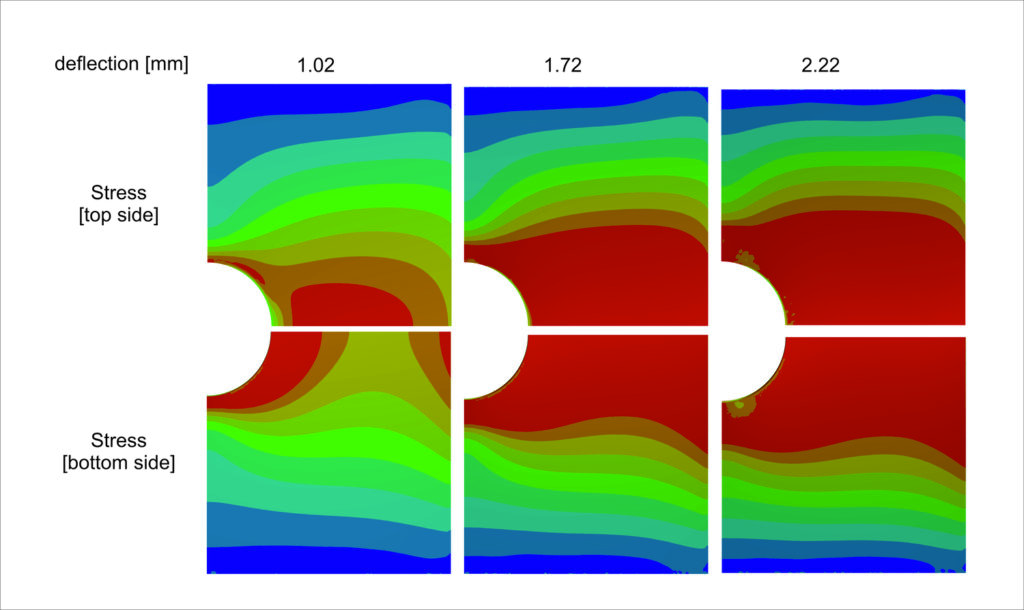
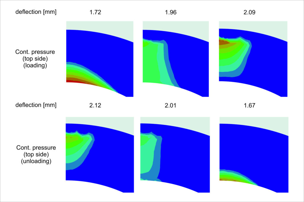
The calibrated model also contributed to elucidating the cause of the significant sharp break in the stiffness curve, manifesting as a notable increase following plasticity-induced decrease. As depicted in
the figure below, this phenomenon arises from a distinct change in the character of the contact pressure distribution between the pin and the spring. The concentration of the contact pressure shifts away from the center of the applied apparatus, diminishing the distance between the applied force and the support (contact between the spring and the frame). Consequently, this alteration increases the force required to achieve a specific deformation. The evolution of contact pressure during unloading follows a similar pattern.
